January 2020
16-bit Counter Prototype Testing
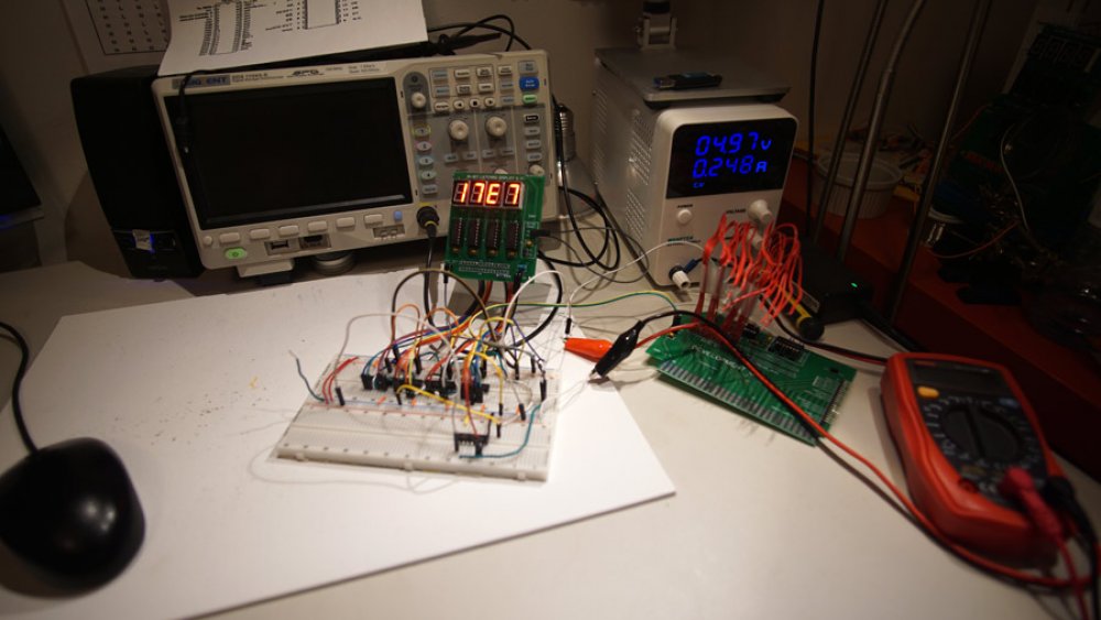
I made some modifications to the counter prototype, including gating the clock with a 74LS08 (quad AND gates), but it seems to have picked up some quirks. I was not able to adequately test at 10Hz... it was just fast enough to make it hard to catch errors with the naked eye, but just too slow for my oscilloscope. I ended up soldering up a second 555 based clock, this time running at a sedate 0.5Hz, giving me nearly two seconds to see each increment or decrement.
At the slower speed the issue became clear. The low 4-bits were displaying values out of order, and the issue turned out to be a couple of crossed jumper wires between the first counter IC and the first mc14995 display driver. Those crossed wires should have been an obvious place to start, but at 10Hz I could not tell the first digit was displaying values out of order, I was barely able to see that it seemed to skip values.
The interesting part to all of this is I learned of a limitation of oscilloscopes (or at least, the Siglent 1104X-E), namely they cannot "scope" frequencies below 10Hz. I honestly had no idea there was a lower limit.
BONUS CONTENT
I tested my first live-stream on Sunday, Feb 2nd, and while the stream is boring (and I do not recommend you watch much of it), the working counter is displayed for the first portion. The distortion and feedback was caused by a friend's video-chat.
I may do live-streams in the future, but they will be planned... I'll be prepared.
16-bit Counter Prototype
The original 8-bit computer design used the 74LS561 counter for the program counter. The 561 is definitely capable, but it is also a bit complex with synchronous and asynchronous operation in a 20-pin package. I tried using a few counters, but the ones I settled on are the 74LS193. This little 16-pin IC allows for loading, resetting to zeros, increment, and decrement. Most of the counter I tried are increment only, including the 561, so I ordered twently 193s and started prototyping when they arrived.
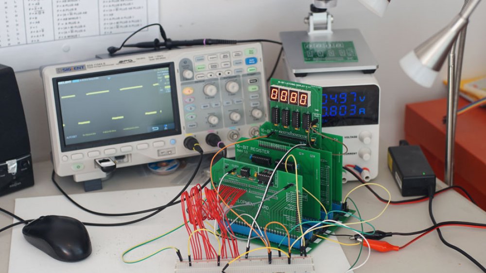
As you can see from the video (or the thumbnail, I won't judge), the 16-bit 193-based counter is working. I tested with load, clear, increment, and decrement successfully. This was with a 10Hz clock provided by the development board (middle, right, with all of the unconnected red wires), and I used one of the 4-digit hex displays for output.
The breadboard wiring looks complicated, but it worked almost perfectly from the start. A problem I did have was with the first 193 not counting. I eventually replaced it to the same effect and finally removed it. This necessitated adding a new forth IC to the left and moving the display wires, but the result was a successful prototype.
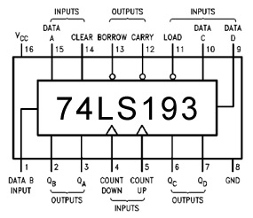
This IC is pretty simple, with a decent pin out. My preference would be for the data pins to be together and in order, but that is seldom the case with TTL components. The main things to look at with this IC are the count up/down pins, and the borrow/carry pins, as these are used to chain the ICs together to create a bigger counter... four of them, for a 16-bit version.
The increment and decrement signals are connected to the count up/down pins of the first (lowest 4-bits) counter IC. The carry from that counter is connected to the count up pin of the next IC, while the borrow is connected to the count down of the next IC. This is the same for the next two ICs, as they carry pin of one is connected to the count up of the next, and so on.
When incrementing, the counter will count to 15 before rolling back to a zero. When it does this, it sends a signal on the carry pin, which acts as the count up for the next IC. So, the first IC increments on every clock (10 times per second, in my prototype), but the second IC increments sixteen times slower.
New Modular Card Design
I have discovered some issues with the PCB designs I have had manufactured, and part of the issue is a lack of consistency. Take bus access, for example. The register card has placement for soldered wires or DIP switches to connect the register to the data or address bus. This is a bit limiting, but works and greatly reduces complexity. The memory card is even less complex, with the data pins linked to the data bus and the address pins linked to the address bus. When it comes to the counters, I want more flexibility to use them on either bus and as transfer registers between the buses. If the ALU can write to either bus, it can act as a partial transfer register... but it will need to be able to read from either bus for this to be useful.
Status and Control Register
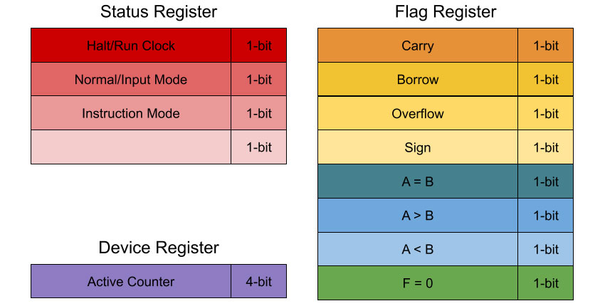
There are various flags that need to be set for the computer to work correctly, such as a carry flag when an arithmetic operation results in a value larger than 16-bits.
Halt / Run
This flag is used to determine in the clock run or not. When the clock is not running, the user can single-step through a program manually. Useful at the end of a program to preserve output, or during execution for breakpoints. Can be set by the user, by an instruction, or perhaps by an error (hopefully),
Normal / Input
In normal mode, the PC increments via the clock (or the single step button, if the clock is halted). When in input mode, the user is able to program the computer via front-panel controls.
Instruction Mode
This mode determines how an instruction is processed by the control logic. If the first digit of an instruction in RAM is a zero, the instruction is decoded from the instruction register. If the first digit of an instruction in RAM is a one, the remaining 15-bits are treated as an address, loaded into the firmware counter, and this flag is set. This flag will keep the firmware counter in control until a return instruction causes the PC to become active and continue executing instructions in RAM.
Active Counter
This 4-bit register indicates which counter is in charge of the address bus (effectively, which counter is the current program counter).
Program Counter
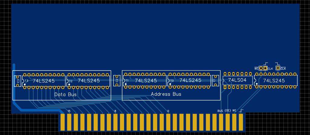
Counters are critically important in any computer, as the Program Counter, loop counters, various other address registers, stack pointers, etc. In my design, pointers can load from either bus, output to either bus, increment, and decrement. To accommodate this, I plan on using 74LS193s, which are two state 4-bit counter ICs. Each bus will require transceivers to control access to and from the counter, and an additional transceiver is required to control the output from the counters, as they are always outputting their value and this would conflict with data or address information being read from a bus.
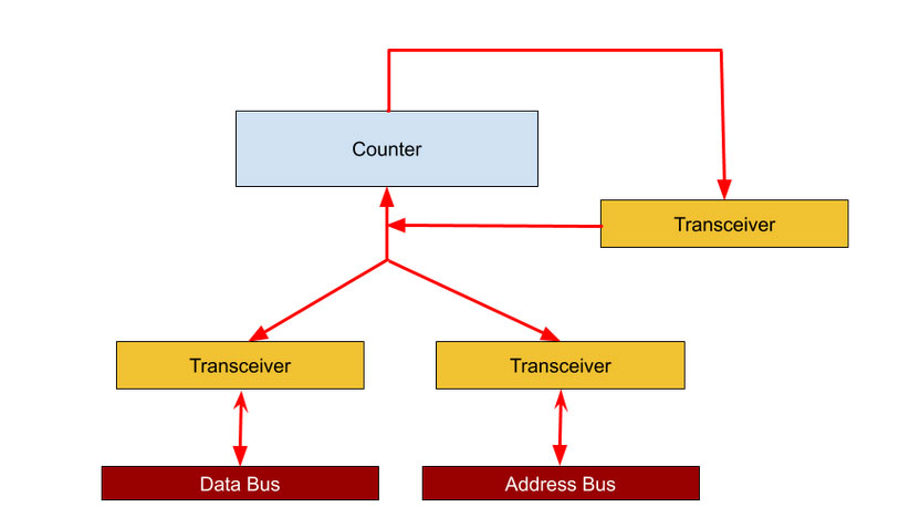
Technically speaking, this will require ten ICs. I will need two 74LS245 transceiver ICs for the data bus, and two more for the address bus. An additional two 74LS245s are required to to enable and disable the counter output (again, to prevent conflicts when reading a bus). The counters themselves will comprise four 74LS193s. These ICs are 4-bit up/down counters with load and reset. I still need to prototype a counter on breadboard, but it is possible I will need an additional inverter IC (perhaps the 74LS06 hex inverter) to simplify the control signals.
What are the benefits of this design?
- Counters can store values from either bus.
- Counters can output values to either bus.
- Counters can reset to zero, increment, and decrement.
- Counters can act as transfer registers between the data and address bus.
- Counters can act as loop counters, with the carry and borrow pins acting as flags for > FFFF and < 0000.
- The ALU can write directly to any counter.
It is going to be pretty complex to design, unfortunately. More on that in a later post.
Successful Register Test
Bad breadboards have been the bane of this project, even when the circuits I am testing are on PCB. The last few register transfer tests failed because the data would corrupt or not actually save, and a few times the stored data in a register would change. I added 1k pull-downs to the data bus today, and it seemed to help, but constant glitches continued.
With the help of a new breadboard, I was able to successfully load values into Register-1, copy those values to Register-2, load a different value into Register-1 (clearing it, basically), then copy the value from Register-2 back to Register-1. I tested with the oscilloscope, and used the 16-bit display boards to see the values being moved around.
The next step is to build additional registers, then design the counters that will be used for memory addressing. Once we are at that stage, looping tests (driven by an arduino or raspberry pi) will be useful again.
Signals and Bus Termination
I remember learning about SCSI controllers, and hearing about termination. At the time I did not know what it meant, just that SCSI cables needed to be terminated for "some reason". The same is true for the computer I am building, the backplane (particularly the two two 16-lane buses) needs termination as well.
What is termination? Why do I need it?
In my case, termination really means pull-down and pull-up circuitry to eliminate glitches caused by floating voltages.
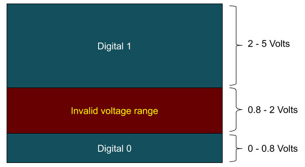 In theory, the computer is digital, passing values of "0" and "1" around... but in reality, it is an analog device where a certain voltage range indicates a "0" and another voltage range indicates a "1". Between these two ranges, there are voltages that are effectively invalid.
When voltages float between 0.8 and 2 volts, the computer will react unpredictably. Voltages are, at least in a computer like I am building, difficult to keep at exact levels.. transistors switching on and off, leaking voltages from ICs, even noise from outside the computer can add up to an "invalid" voltage reaching the low or high range and triggering an unwanted "0" or "1" response.
To prevent floating voltages from leading to problems, we will use pull-down and pull up resistors. A pull-down resistor is just a resistor between the floating pin or lane and ground. This effectively increase the voltage range that will be treated as a digital "0", by lowering the voltage by an amount. For example, if a -1 volt pull-down is implemented, a digital "0" will be seen for any voltage applied to that pin or late between 0 and 1.8 volts.
There is a lot of interesting math one can use to calculate the appropriate values for pull-down and pull-up resistors, but I am a prototyper so you will not see that math here. Instead, I try various resistor values until I find ones that work.
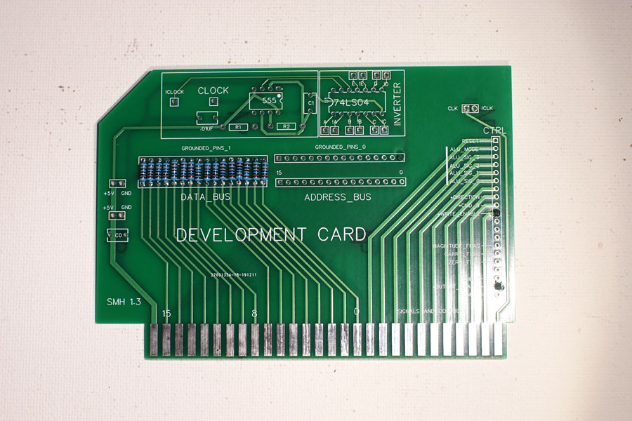
Using a connection/development board, I have added1k resistors between the 16-lanes of the backplane and ground. The purpose of this is to pull the bus low as a default, and 1k is a compromise for the first attempt.
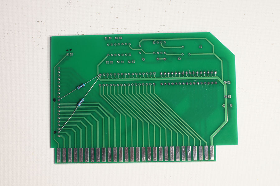
I also added 1k pull-down resistors to the Output Enable and Write Enable signals on this card, for testing purposes. These pins are not shared , so they will not act as pull-downs for any other card... but I have some tests in mind that they will be useful for.
The next step is to set the computer back up and test moving values between resistors again.