04 - Control Logic
Instructions, Decoding, and Timings - Part 1
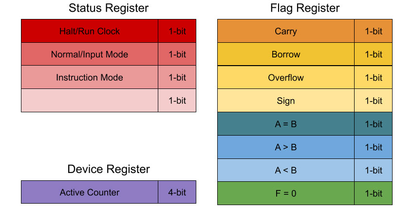
Status and Control Register
There are various flags that need to be set for the computer to work correctly, such as a carry flag when an arithmetic operation results in a value larger than 16-bits.

Halt / Run
This flag is used to determine in the clock run or not. When the clock is not running, the user can single-step through a program manually. Useful at the end of a program to preserve output, or during execution for breakpoints. Can be set by the user, by an instruction, or perhaps by an error (hopefully),
Normal / Input
In normal mode, the PC increments via the clock (or the single step button, if the clock is halted). When in input mode, the user is able to program the computer via front-panel controls.
Instruction Mode
This mode determines how an instruction is processed by the control logic. If the first digit of an instruction in RAM is a zero, the instruction is decoded from the instruction register. If the first digit of an instruction in RAM is a one, the remaining 15-bits are treated as an address, loaded into the firmware counter, and this flag is set. This flag will keep the firmware counter in control until a return instruction causes the PC to become active and continue executing instructions in RAM.
Active Counter
This 4-bit register indicates which counter is in charge of the address bus (effectively, which counter is the current program counter).
