November 2019
Backplane PCB
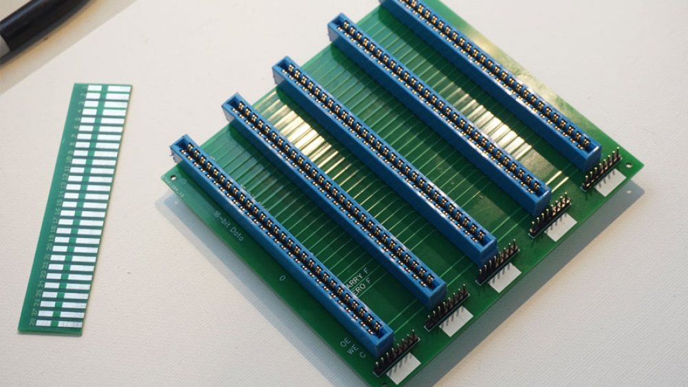
I ordered five backplane PCBs, and received them on November 27th. They turned out really well, except I did not leave space for the screw mounts on the ends of each JAMMA edge connector. The solution involved cutting the screw months off with a hacksaw, but the end result was the first two backplanes soldered and 100% tested.
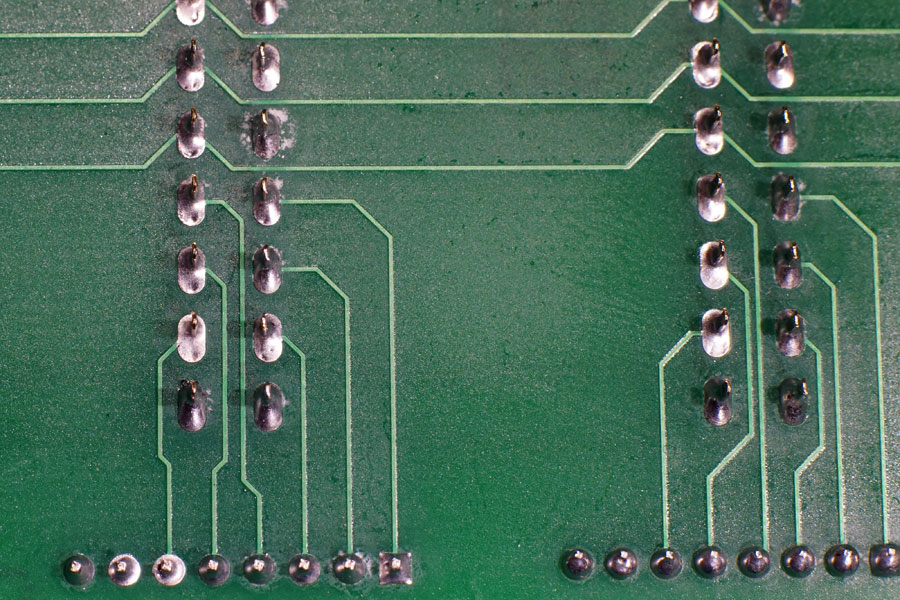
My soldering skills are pretty low, but the results turned out okay. The zoomed in shot shows the 6-lane breakout point for two of the connectors.
Downloads
Backplane Design
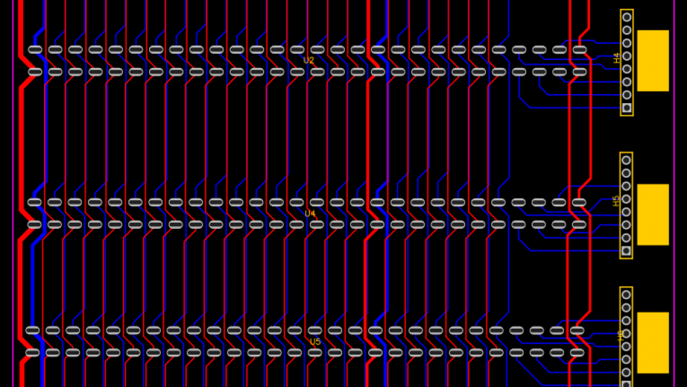
My first PCB design is the backplane, as it is relatively simple and will be needed by every subsequent PCB. It took a couple months of research, but I settled on JAMMA style edge connectors giving me a total of fifty-six lanes between the cards. I decided to break six lanes out to separate "card select" headers, so only fifty lanes are tied in parallel across the edge connectors.
To keep costs down, each board contains only five JAMMA connectors, plus pinheaders. I should have designed interconnects, to make linking boards easier, but the end result is a backplane allowing a maximum of twenty-five connected devices. I will need to order additional (or replacement) PCBs to expand beyond twenty-five connections, but I do not expect to need more than twelve or fifteen.
16-bit CPU - Backplane Concept
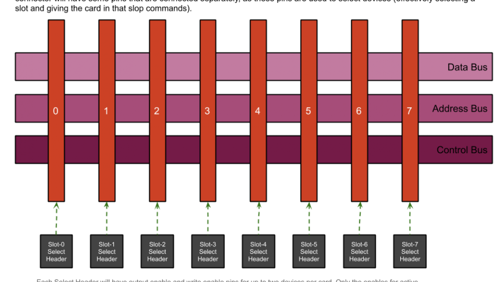
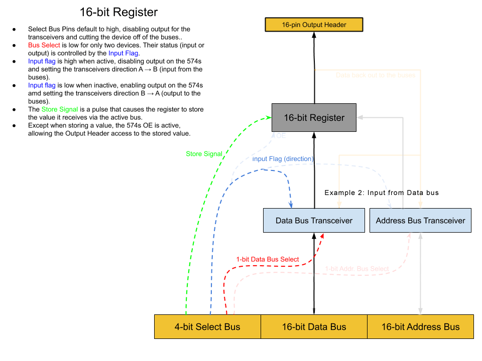
After a month of crazy plans and ideas, I settled on the idea of a backplane providing access to a 16-bit data bus, a 16-bit address bus, clocks, power, and control buses.
Some Discarded Design Concepts
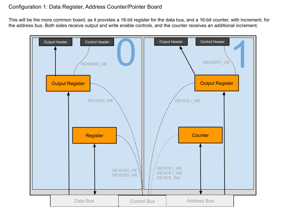
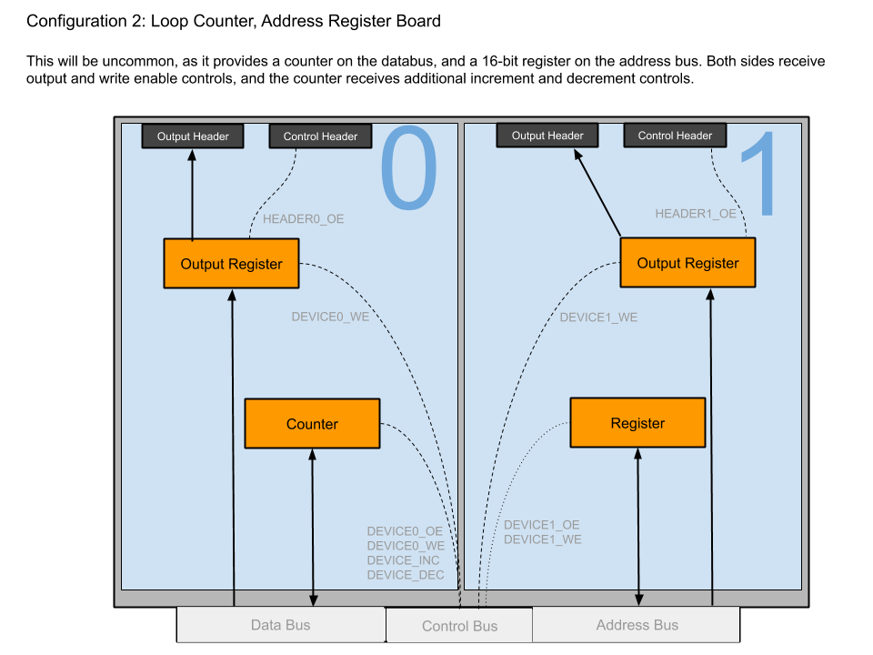
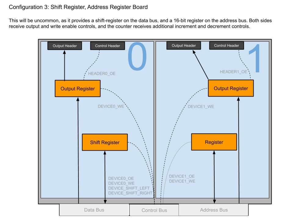
In no particular order, here are some architectural designs I briefly considered for the 16-bit CPU.
.png)
.png)
.png)
