Signals and Bus Termination
I remember learning about SCSI controllers, and hearing about termination. At the time I did not know what it meant, just that SCSI cables needed to be terminated for "some reason". The same is true for the computer I am building, the backplane (particularly the two two 16-lane buses) needs termination as well.
What is termination? Why do I need it?
In my case, termination really means pull-down and pull-up circuitry to eliminate glitches caused by floating voltages.
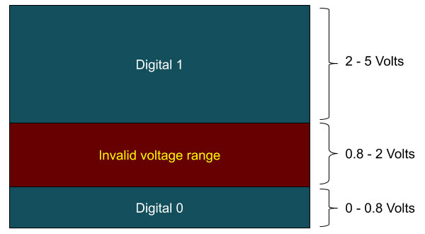
 In theory, the computer is digital, passing values of "0" and "1" around... but in reality, it is an analog device where a certain voltage range indicates a "0" and another voltage range indicates a "1". Between these two ranges, there are voltages that are effectively invalid.
When voltages float between 0.8 and 2 volts, the computer will react unpredictably. Voltages are, at least in a computer like I am building, difficult to keep at exact levels.. transistors switching on and off, leaking voltages from ICs, even noise from outside the computer can add up to an "invalid" voltage reaching the low or high range and triggering an unwanted "0" or "1" response.
To prevent floating voltages from leading to problems, we will use pull-down and pull up resistors. A pull-down resistor is just a resistor between the floating pin or lane and ground. This effectively increase the voltage range that will be treated as a digital "0", by lowering the voltage by an amount. For example, if a -1 volt pull-down is implemented, a digital "0" will be seen for any voltage applied to that pin or late between 0 and 1.8 volts.
There is a lot of interesting math one can use to calculate the appropriate values for pull-down and pull-up resistors, but I am a prototyper so you will not see that math here. Instead, I try various resistor values until I find ones that work.

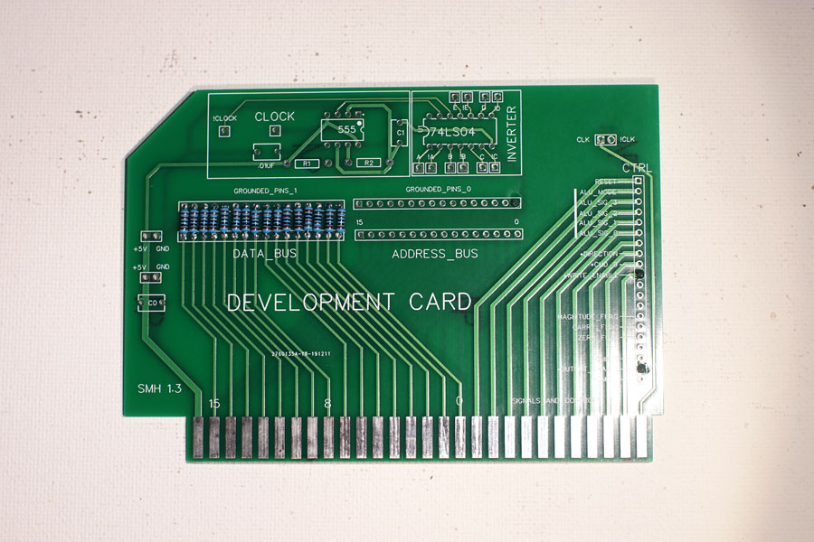
Using a connection/development board, I have added1k resistors between the 16-lanes of the backplane and ground. The purpose of this is to pull the bus low as a default, and 1k is a compromise for the first attempt.

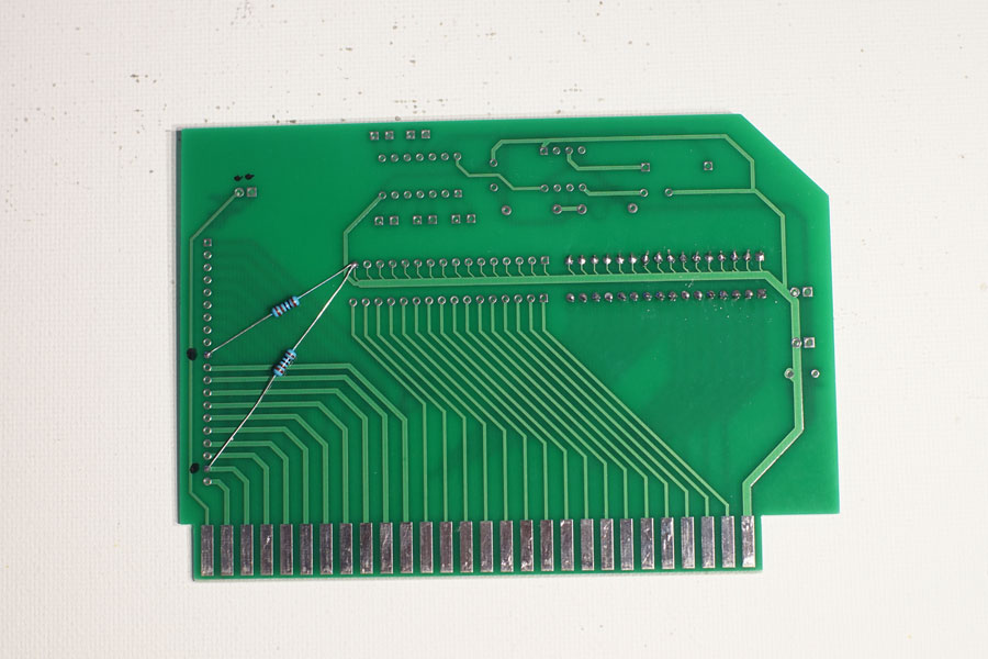
I also added 1k pull-down resistors to the Output Enable and Write Enable signals on this card, for testing purposes. These pins are not shared , so they will not act as pull-downs for any other card... but I have some tests in mind that they will be useful for.
The next step is to set the computer back up and test moving values between resistors again.
