16-bit Counter Prototype - Round Two
The 16-bit counters are successfully driving registers and displays attached to the backplane. I did some testing with the "autorouted" SRAM card, but I only had the data bus connected. For this test, I was running the 10Hz clock and all controls were via the appropriate connections (i.e. the backplane), except where the breadboard was involved.
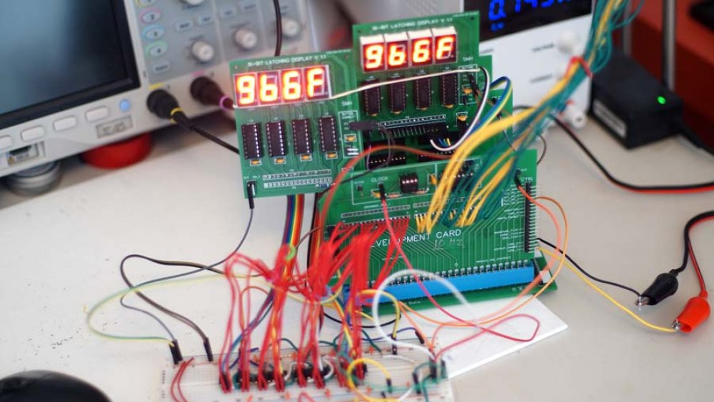
The display on the left is connected directly to the outputs of the four 74LS193 counters on the breadboard. The counters get power and the clock (via the 74LS08 "gate") from the development card (at the front of the backplane). The red lines between the breadboard and the development card link to the backplane's data bus. The development card has the 555 timer circuit providing the clock to the backplane and the breadboard. The display on the right is attached to the monitor header of a 16-bit register card, and displays the output from the register. The ram card (not visible in the photo) was storing the data bus value at whatever random addresses the 16-unconnected wires was generating.
This test was to ensure the bus was working correctly, and that timing issues do not appear (at low frequencies, anyway). The next step will be to test writing to memory, then reading the values back. I do not have an input rig setup, so I will probably end up using an arduino for data reading and later checking.