16-bit Hex Display Board
I have wanted a decent display system since I started this hobby in 2015, and finally had the opportunity to create something. The front-panel that I have planned will display binary output for the (control, signal, data, and address) buses, but will have four-digit hex displays for registers. The reason for this is it is much easier to quickly see values when they are displayed in hexadecimal, but binary is obviously better for showing which bits are set.
This display board was designed in EasyEDA, directly as a PCB... so no schematic. I probably should have created a schematic first, but I am a prototyper at heart and it feels better to me to lay out PCBs the way I lay out breadboards. I never draw circuits before breadboarding, so I am trying to do the same with these PCBs.
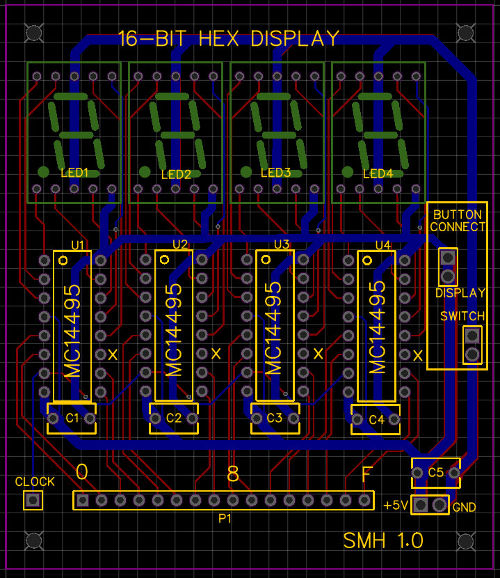
This is not the final version, but it is close and I wanted to compare it to the final version I had made. Because I do not do schematics, I end up laying out the PCB several times as I refine the components and positioning. This board is relatively simple, as it just needs four MC14995s to drive four 7-segment common cathode displays. I added a 16-pin header to connect the board, a clock pin, and power. Because I plan to use these with a front panel, there are pins to connect to controls... but for stand-alone use the switch pins can be shorted or jumpered. The decoupling capacitors are optional.
So, what was wrong with this design? Several things. First, I had planned to mount the displays on the reverse side, but I became confused during the layout and did not lay the traces 100% correctly. A second issue was the 16-pin header... really, I needed two so that the display could act as a pass-through.
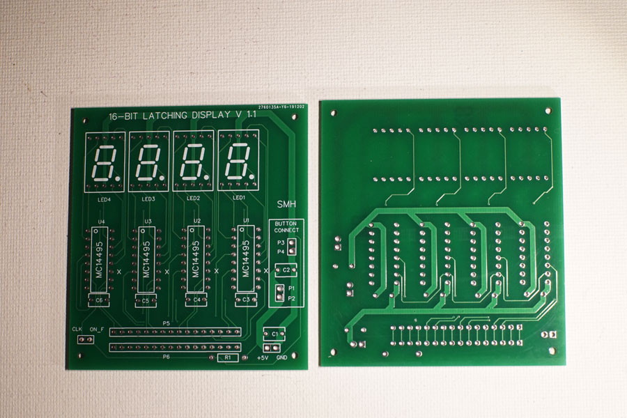
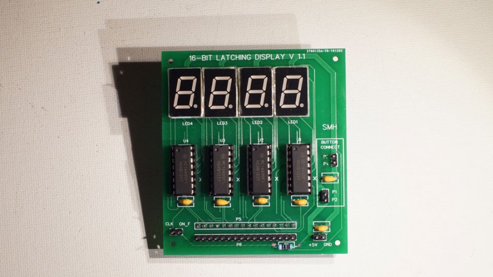
The final version is very similar to the 1.0 version, with the most notable exceptions being the displays and an extra 16-pin header. Front-panel related pin headers have been adjusted as well. The R1 resistor on the bottom of the board is a pull-up for the "on flag" pin.
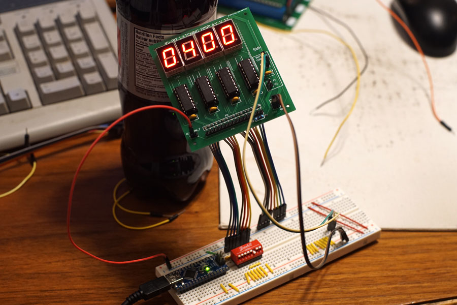
Fully populated, the hex display board was tested with a breadboard, 8-bits at a time (I only had one dip switch unit handy).
I have enough PCBs to build ten display boards, but I probably only need five or six, maybe a couple more for other projects.