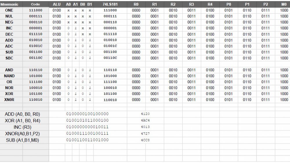
ALU Instructions

The 74LS181 is an interesting IC, but one of the benefits of it is the host of functionality it provides access to. This IC takes a mode signal to switch between logical and arithmetic functions, four signals to indicate the function, and a carry that changes what arithmetic functions are able to do. For example subtraction is either A - B or A - B - 1, depending on the carry flag.
In this computer, with 16-bit instructions, ALU operations are indicated by 0100, and perhaps 0101 (but I will speak about that in a future post, after some testing). These four digits lead the instruction, so (from a hexadecimal view), all ALU functions will start with a hex 4. The next two digits indicate source for the "A" register and "B" register inputs. When combined, this means the ALU function and source inputs take up 8-bits, and give us two hex digits in the middle. This is followed by the actual ALU instruction, which is six digits in total. Finally, a four digit target is included, making the target a human readable "0 - F".
Examples:
#4xx3 - ALU function xx, store the result in device 3
#4xxF - ALU function xx, store the result in device 15
#4xxA - ALU function xx, store the result in device 10.
The two hex digits for the function are more complicated, but should be human readable with a simple lookup table.
Non-ALU Plans
Each operation starts with a 4-bit system identifier, followed by a 4-bit function, and one or two 4-bit identifiers. This means other instructions should be human readable in hex format. Where a "system" needs more than sixteen possible functions, we can allocate additional "system" codes, or break the instructions up... conditional operations (like branching) might be organized into a separate block from unconditional operations (like jumps), and two-part operations (memory related) into their own as well.
Example:
#1xE7 - A "system 1" function, using device 14 as the source and device 7 as the target.
