January 2020
Instruction Design, 4-bit Device Identification
I want 5-bit identifiers so that I can have more than ample devices on the backplane, but the reality is coding will be much simpler with 4-bit chunks... each part of an instruction can be indicated with a single hexadecimal character.
.png)
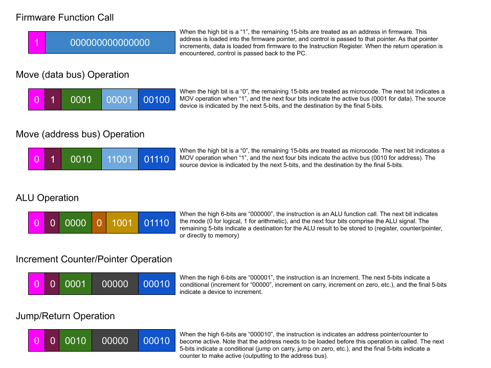
The first digit of any actual instruction will be zero and can be ignored. The next 6-bits are the actual "instruction" in most cases, and is blocked in purple. The orange bit indicates a mode or status, and is not always required. The light blue block indicates a source device and the darker blue a destination or target device. A red block indicates the 4-bit ALU signal. The 4-bit black block indicates the source for conditionals... 0000 meaning the instruction is not conditional, 0001 meaning the instruction occurs when the carry flag is set, etc.
Instruction Parts Plan
I believe it will be easier to design and prototype the Instruction Register and control logic if I know what the instruction values will be, so I am prototyping the format of microcode. This image is subject to change, but really helps me to visualize microcode instructions.
MOV Instruction - 4-bit Device IDs
I will start with the plan for 4-bit device identification. This allows a source and destination to each be a single hex digit, making it much more human readable. Peripherals can be identified by their own 4-bit identifiers, with the leading instruction providing content. This means more leading instructions, but I believe it will be worth it... and sixteen devices will be sufficient to start anyway.
Device Binary Hex
0 0000 0
1 0001 1
2 0010 2
3 0011 3
4 0100 4
5 0101 5
6 0110 6
7 0111 7
8 1000 8
9 1001 9
10 1010 A
11 1011 B
12 1100 C
13 1101 D
14 1110 E
15 1111 F
I have three completed registers now, so it is possible to start prototyping the Instruction Register and the control logic for a MOV instruction to copy values from one register to the next. In the prototype, the IR can actually be 16-lane dip switches. To that end, I need to actually pick a code for the MOV instruction.
If the highest order bit is the instruction mode (1 for firmware address, 0 for microcode), that means that the first hex digit must be a 7 or less. Any value of 8 or higher will indicate that the remaining 15-bits are an address in the EEPROM bank.
OP Code Example Instruction Description
0A{sd} 0A1F MOV S, D Move a value from source to destination.
The control logic needs to decode this in parts. For now, I will assume the decoding is in 4-bit chunks.
0000 - Ignore
1010 - MOV
0001 - Source Device
1111 - Destination Device
MOV Instruction - 5-bit Device IDs
While 4-bit identifiers are straight forward to use, 5-bit identifiers greatly expand the potential of the computer. Using 10-bits to identify source and destination only leaves us with 6-bits for the rest of the instruction, 5-bits when we take the instruction mode bit into consideration. With three 5-bit pieces, we do not have a stable opcode for the "MOV" portion of the instruction... each hex character is made up of 4-bits.
Device Binary Hex
0 00000 0
1 00001 1
2 00010 2
3 00011 3
4 00100 4
5 00101 5
6 00110 6
7 00111 7
8 01000 8
9 01001 9
10 01010 A
11 01011 B
12 01100 C
13 01101 D
. . .
30 11110 FE
31 11111 FF
If the highest order bit is the instruction mode (1 for firmware address, 0 for microcode), that means that the first hex digit must be a 7 or less. Any value of 8 or higher will indicate that the remaining 15-bits are an address in the EEPROM bank.
The control logic needs to decode this in parts, and in this case it would be in unwieldy 5-bit chunks.
010000 - MOV
00001 - Source Device
01111 - Destination Device
An alternative to this would be to combine the source with the MOV instruction and make the destination 8-bits (padded with zeros from 5-bits)
M04, 1E - Move the value from device #4 into device #1E.
MFF, 09 - Move the value from device #FF into device #9
I do not like this, it is not an elegant solution, it wastes instruction bits, and it means numerous duplicate instructions. I think I need to stick to 4-bit identifiers. Fifteen devices (plus the zero register) will limit the number of devices I can use effectively with the MOV instruction, but other instructions may be more flexible..
Instruction Length and Components
For register to register type instructions, I wanted to go with 5-bit identifiers. This leaves 6-bits for the command, and allows for thirty-two connected devices. This may be overkill, as 4-bit identifiers still gives us sixteen devices (0-15), and each device is identified by a single hex value.
The best way to see why this might matter is to compare three MOV instructions, copying values between two registers. With 4-bit identifiers (the left hex instruction) the first two characters indicate the command and the next two a source and destination device. When we use 5-bit identifiers (the right hex instructions), only the first character will be unchanged, the next three will vary depending on the actual device IDs.
4-Bit 5-bit
MOV R01, R10 AA1A vs A82A
MOV R13, R11 AADB vs A9AB
MOV R00, R15 AA0F vs AA0F
It probably does not matter in the long run, I may be using an assembler, but the left examples are clearer and easier to understand than the right.
I will have to give this some thought, as I am not sure 16 devices (15, really) will be enough. Hypothetically speaking, I will need the following:
Planned Device List
0 - Zero/Null Register
1 - Program Counter
2 - Return Register
3 - Firmware Pointer
4 - Firmware Return Register
5 - Variable Pointer
6 - Loop Counter
7 - "A" Register, for ALU
8 - "B" Register, for ALU
9 - General Purpose Register
A - 64K of user programming memory
B - 64k of variable storage memory
C - 64k of firmware
A possibility would be to combine device B and C into one, with 32k of eeprom and 32k of sram. This would be a compromise, but would free a device number.
This is pretty tight, considering it does not include I/O of any kind, any front-panel registers, sound or video systems... but those may work okay as dedicated instructions. This is how the ALU will work.. it does not have a Device ID per say, instead an ALU instruction includes 5-bits for the mode and signals, and 4-bits for a destination device on the data bus. Sound systems, video, LCD output, etc. will probably interface via special registers, but they may not need device numbers the way memory banks or normal registers do. If I go with 5-bit identifiers, we would have twice as many device numbers available and could easily include a dozen different addressable registers.