Instructions
ALU Instructions

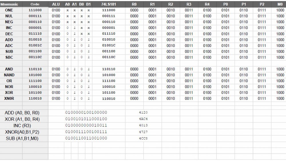
The 74LS181 is an interesting IC, but one of the benefits of it is the host of functionality it provides access to. This IC takes a mode signal to switch between logical and arithmetic functions, four signals to indicate the function, and a carry that changes what arithmetic functions are able to do. For example subtraction is either A - B or A - B - 1, depending on the carry flag.
In this computer, with 16-bit instructions, ALU operations are indicated by 0100, and perhaps 0101 (but I will speak about that in a future post, after some testing). These four digits lead the instruction, so (from a hexadecimal view), all ALU functions will start with a hex 4. The next two digits indicate source for the "A" register and "B" register inputs. When combined, this means the ALU function and source inputs take up 8-bits, and give us two hex digits in the middle. This is followed by the actual ALU instruction, which is six digits in total. Finally, a four digit target is included, making the target a human readable "0 - F".
Examples:
#4xx3 - ALU function xx, store the result in device 3
#4xxF - ALU function xx, store the result in device 15
#4xxA - ALU function xx, store the result in device 10.
The two hex digits for the function are more complicated, but should be human readable with a simple lookup table.
Non-ALU Plans
Each operation starts with a 4-bit system identifier, followed by a 4-bit function, and one or two 4-bit identifiers. This means other instructions should be human readable in hex format. Where a "system" needs more than sixteen possible functions, we can allocate additional "system" codes, or break the instructions up... conditional operations (like branching) might be organized into a separate block from unconditional operations (like jumps), and two-part operations (memory related) into their own as well.
Example:
#1xE7 - A "system 1" function, using device 14 as the source and device 7 as the target.
Parts of an instruction
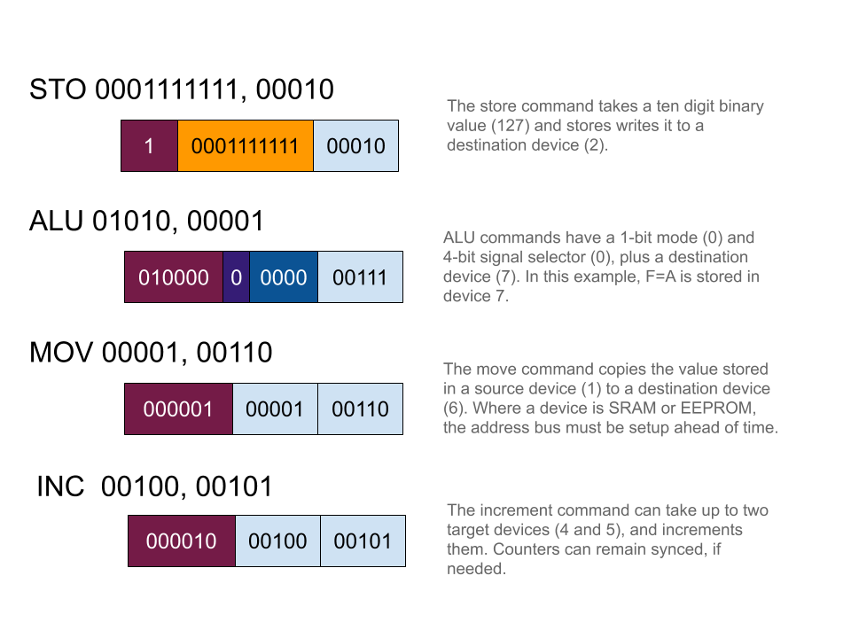
I am still trying to figure out the best format for instructions, and it looks like they will have variable length verbs. For a store command, I think one flag digit and five destination digits are sufficient, and allow for a ten digit binary value. When we are copying values between devices, a total of ten digits are required to identify the two devices. For something like an increment command, we only need five digits for the target... but we have room for two, and it might be useful for syncing counters (coping a range of values from EEPROM to SRAM, for example) so why not allow up to two counters to increment at a time?

This is all subject to change, but working through possible instruction structures is definitely useful.
