16-bit Register Board
I had a lot of different plans for the 16-bit register, but all of them had two basic requirements:
- The PCB needs to work for both data-bus and address-bus registers.
- The PCB needs to have an "always on" header (for the front-panel or ALU)
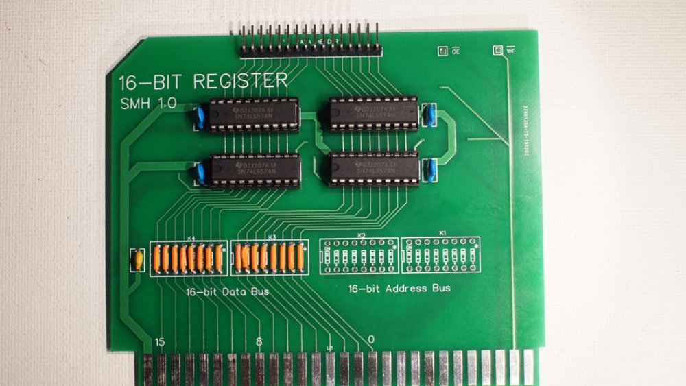
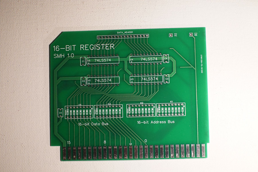
I would prefer to design registers for specific uses, but when having PCBs manufactured it was more economical to try to combine designs as much as possible. Because of that, the PCB links the data and address-buses to the 74LS574 ICs, with breaks that I could jumper when populating the boards. To accomplish 3-state bus access but have the register value always available to a 16-pin header, I went with a second set of 74LS574s that store with the register ICs, but always outputs to the header. This adds about $2 to the cost of populating a register board, so in instances where the header might never be used, those extra ICs can be left out.
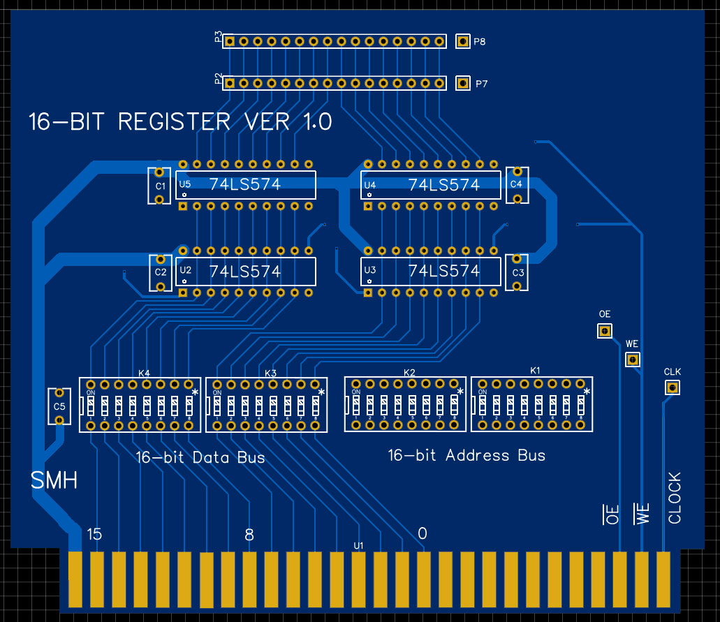
This design was created by hand as a PCB, without a schematic. I explain my reasoning in the Hex Display post, but basically I design PCBs the same way that I lay out breadboards... I grab the datasheets and start connecting pins. This is inefficient, and requires multiple iterations before I am happy with a design, but it feels better to me. In this case, this was not the final design but it makes an interesting contrast to what was produced. If you compare them, the main difference is how the signal test pins are located. The "clock" was dropped from this board, as the actual clock signal will be gated to this card and transmitted on the write enable line.
I also dropped the second 16-pin header on the top, as the display board was updated to act as a pass-through when necessary.
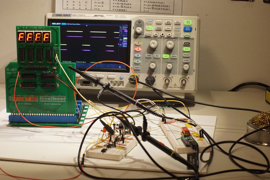
Fully populated, the register board was tested with my first display board. The oscilloscope probes are connected to the output of the 555 timer (on the foreground breadboard) and the clock test pin on the display board... I wanted to see how if the clock waveform deforms or picks up any noise. Unfortunately, when I took this photo I had the oscilloscope in "roll mode" so the waveform looks a bit dirty.
I have enough PCBs to build ten register boards, but I will start with three... A-Register and B-Register for the ALU, and one general purpose register. I might also populate an address register or two once I start programming branching and jumps.