Instruction Set Design
To design the lowest level instructions, I need to know the hardware involved... and I have spent months going back and forth on different architectural questions brought up while working on an instruction set. In many cases, I settled on a design and proceeded only to discover a painful inefficiency that that design was going to bring to the code.
This instruction set is based on a three-bus design. There are two data buses that the devices can read from and write to, and one small address bus that feeds system memory. Why two data buses? The ALU has two inputs and one output, with each of the data buses acting as an input and results being stored to an internal Accumulator. This means flags are updated right away when performing ALU functions, but accessing the results can be delayed to the next cycle.
ALU Examples:
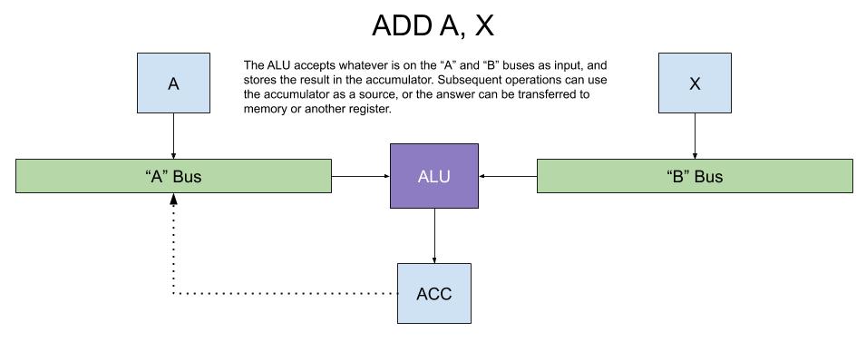
The simplest operation involves two registers, in this case the A and X-registers. They are set to output on their respective buses, and the ALU performs the operation. The results can be output to the "A" bus on a subsequent cycle.
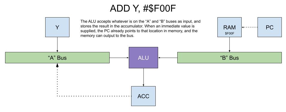
When adding an immediate value, that value follows the instruction in main memory. Because we increment the PC after fetching an instruction, it should already be pointing at the location, so (much like the register - register example above) we can output memory to the "B" bus while "Y" outputs to the "A" bus. As before, the results are stored in the Accumulator.
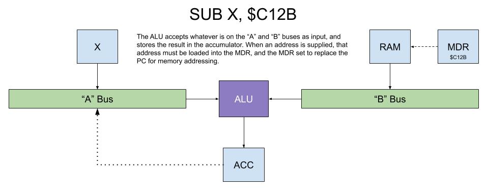
When an absolute address is involved, an extra step is required. In this case, the value following the instruction (addressed via the PC) is output to a data bus and loaded into the Memory Data Register. On the next cycle, memory located at the MDR, is output to the "B" bus and used by the ALU as in the previous examples.
When an indirect or relative address is required, the ALU may need to calculate an address and then move it from the Accumulator to the MDR instead.
Jump Examples:
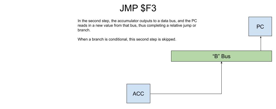
When a jump or branch occurs, the contents of the PC are updated. In this example, a relative jump is performed, requiring the new address to be calculated. In reality this would mainly be for relocatable code, but similar functionality could be used with the Memory Data Register to loop through arrays in memory.
The first step for a relative jump is to calculate the new address by adding the current address (from the PC) with an offset (from the instruction). The Instruction Register is masked so that when it outputs to a data bus, only the low 8-bits are available. In this example, the address offset is -13 in decimal.
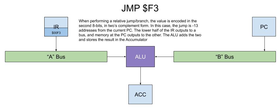
The second step involves updating the PC with the calculated address.