Connection/Development Board #1
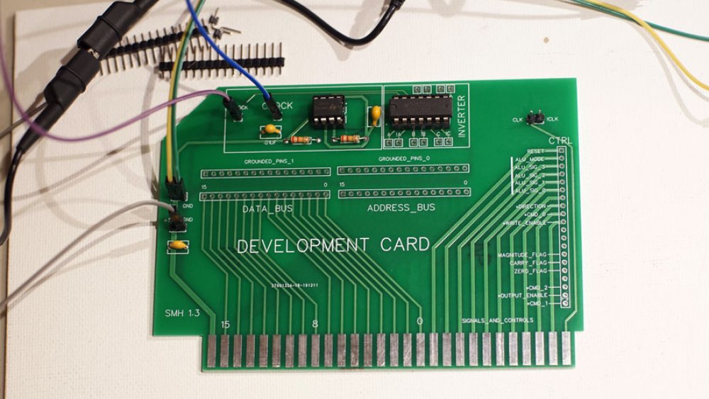
The first connection board has been partially assembled and was ready for the first round of tests to make sure my timer circuit works. For this first board, I setup a 10Hz astable 555 timer, with the the output going to a test pin. The output also goes to a 74LS04 hex inverter to give me a second, inverted, clock signal.
I tested by hooking channel 1 (yellow trace) of the oscilloscope to the 555 output, and channel 2 (purple) to the inverted 555 output.
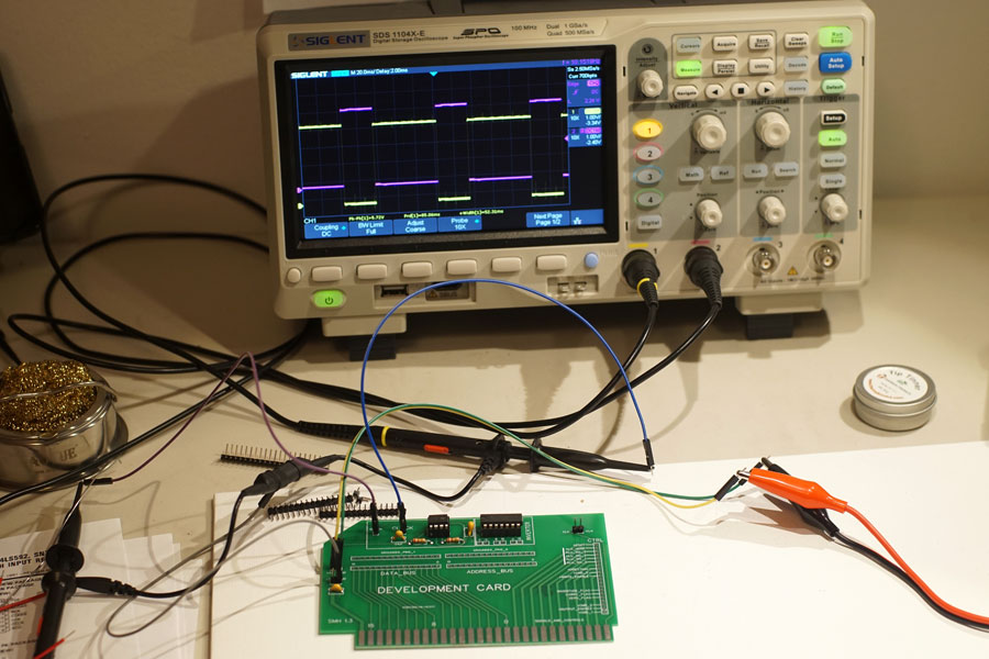
I adjusted the two channels to make it easy to see the two square waves, and it looks pretty good. The only possible concern is what appears to be a fair bit of noise when the signals are low. The long, unshielded test leads are probably responsible, but I plan on further testing.
All that remains is to solder on the 16-pin headers and this first connection/development board will be complete.