StephenHermer.com
Writing, Iguanas, and Electronics

04 - Control Logic

Instructions, Decoding, and Timings - Part 1

For me to understand the fetch, decode, execute cycle... well, I need to work through it, I guess. So, here is my first crack at the clock timings for the four possible MOV operations. 
 
MOV Reg, Reg    ; Register to Register
MOV Reg, $0000  ; 16-bit Value to Register
MOV Reg, #0000  ; Register to Memory
MOV #0000, Reg  ; Memory to Register 
 
The above are planned assembly code instructions for moving data between registers, loading values into a register, and moving values between registers and memory. The ALU will output to registers and memory as well, but I will leave that until much later.
 
 
001-MOV_(R,R).jpg
The "Register to Register MOV" operation is pretty simple. The instruction is fetched and decoded, and the PC is incremented during the first step. The second step is the execute phase, where one register outputs and on the rising clock, the other register writes. I have provisions for delayed and inverted clocks in my design, but I am hoping they will not be needed to prevent timing issues.


002-MOV_(R,V).jpg
The "Value to Register MOV" instruction is basically the same as the Register to Register version. Because the PC was already incremented, the correct address is loaded and we need only output from memory and write to the selected register. The PC needs to be incremented a second time, to ensure the next fetch operation is on an instruction and not the value we just copied to a register.


003-MOV_(R,M).jpg
A "Memory Location to Register MOV" is a little more involved, as the address needs to be loaded into a separate pointer and made active. Like the Value to Register MOV, the PC needs to be incremented once to make sure it points to the next instruction. On the third step, the memory (as addressed by the temporary address register) outputs, and the selected register writes. The PC needs to be made active once the memory operation is completed.


004-MOV_(M,R).jpg
The "Register to Memory MOV" instruction is nearly identical to the "Memory to Register MOV", with only the final output and write targets switched. 
 
 
Comments
Login to post comments.

Status and Control Register

There are various flags that need to be set for the computer to work correctly, such as a carry flag when an arithmetic operation results in a value larger than 16-bits.
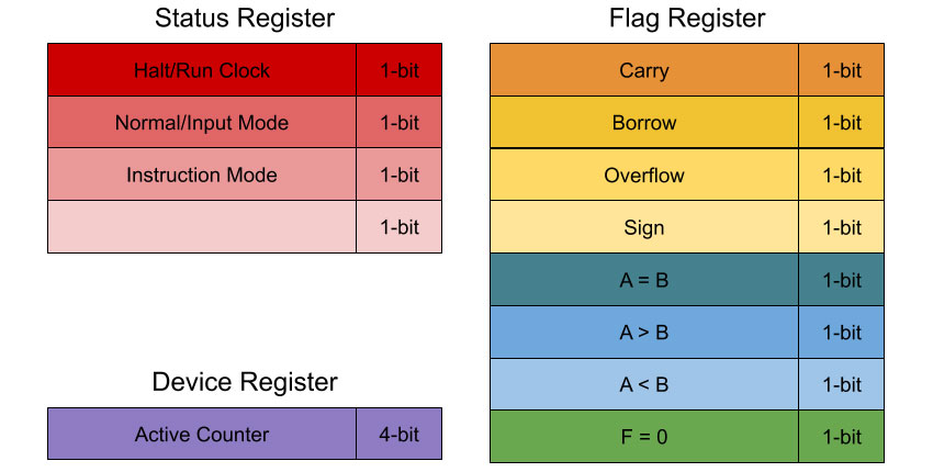
Halt / Run
This flag is used to determine in the clock run or not. When the clock is not running, the user can single-step through a program manually. Useful at the end of a program to preserve output, or during execution for breakpoints. Can be set by the user, by an instruction, or perhaps by an error (hopefully),

Normal / Input
In normal mode, the PC increments via the clock (or the single step button, if the clock is halted). When in input mode, the user is able to program the computer via front-panel controls.

Instruction Mode
This mode determines how an instruction is processed by the control logic. If the first digit of an instruction in RAM is a zero, the instruction is decoded from the instruction register. If the first digit of an instruction in RAM is a one, the remaining 15-bits are treated as an address, loaded into the firmware counter, and this flag is set. This flag will keep the firmware counter in control until a return instruction causes the PC to become active and continue executing instructions in RAM.

Active Counter
This 4-bit register indicates which counter is in charge of the address bus (effectively, which counter is the current program counter).


Comments
Login to post comments.